Create your own electronics parts in Fusion 360: Video 2 - Making a Symbol
Blog
Introduction
Welcome to OrangeCoastWeb, your trusted partner for outstanding website development services in the Business and Consumer Services industry. In this article, we will delve into the fascinating world of creating custom electronics parts using Fusion 360. Follow along as we guide you through Video 2 of our comprehensive tutorial series.
Why Fusion 360?
Before we jump into the specifics of making a symbol in Fusion 360, let's briefly discuss why this software is a top choice for designers and engineers alike. Fusion 360 is a powerful tool that combines CAD, CAM, and CAE capabilities, making it an all-in-one solution for product development. It offers a comprehensive feature set, intuitive interface, and seamless collaboration options, making it an ideal choice for professionals in the design industry.
Understanding the Symbol Creation Process
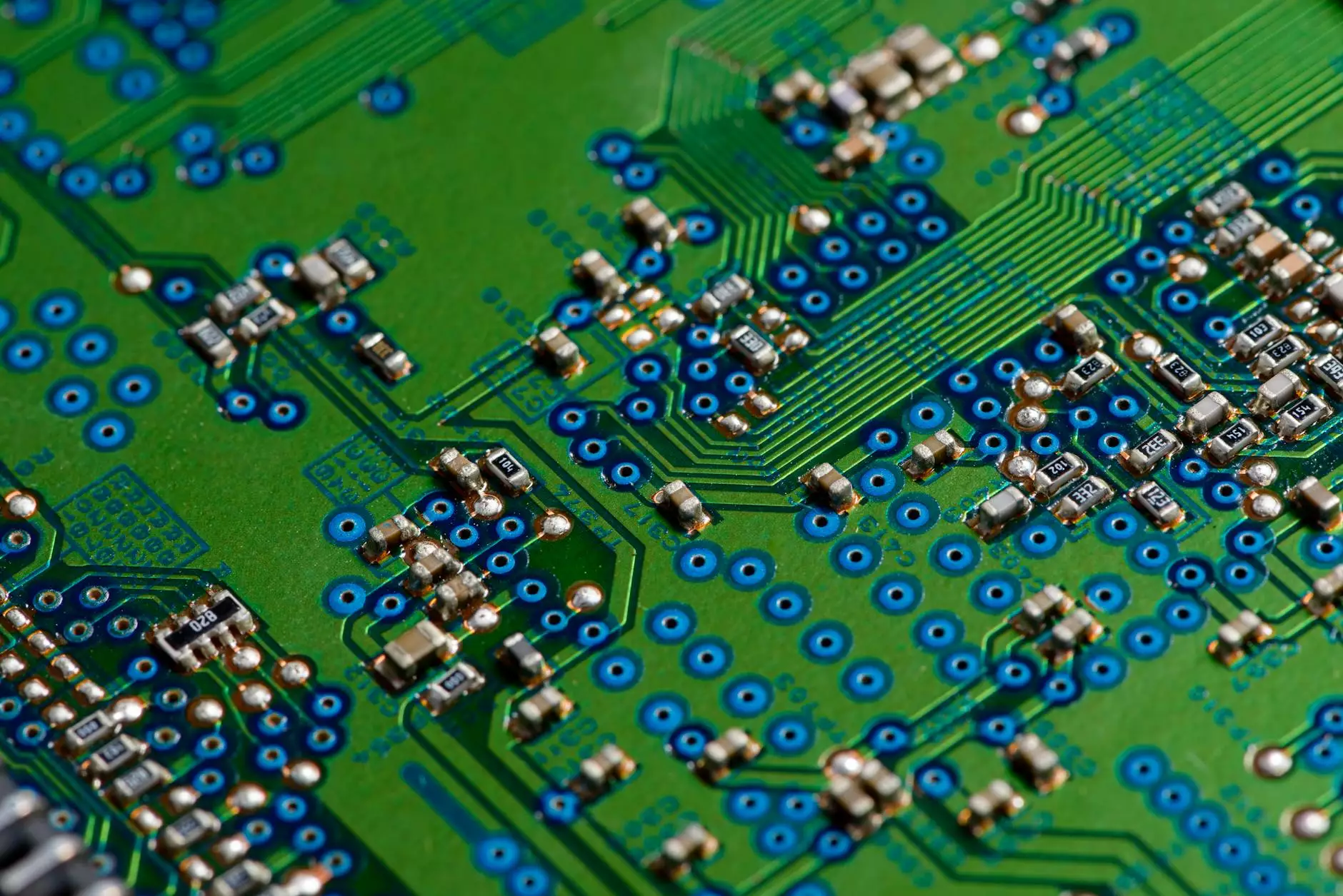
Creating custom electronics parts is a crucial step in the design process, especially when it comes to PCB (Printed Circuit Board) design. Symbols, also known as schematic symbols, represent various components such as resistors, capacitors, and integrated circuits. These symbols provide a visual representation of the electronic component's functionality and connections.
The Importance of Custom Symbols
Utilizing custom symbols in your PCB design offers several advantages. Firstly, it enhances the accuracy and clarity of your schematics, ensuring that each component is correctly represented. Custom symbols also allow for efficient reuse of components, saving time and effort in future projects. Additionally, they enable better collaboration within design teams and facilitate easy integration with other design tools.
Step-by-Step Tutorial: Making a Symbol in Fusion 360
In Video 2 of our Fusion 360 tutorial series, we will guide you through the process of creating a custom symbol for your electronics parts. Follow these steps:
- Open Fusion 360 and create a new Electronics design project.
- Access the Schematic Editor workspace and navigate to the Components tab.
- Click on "Create Symbol" and set the symbol properties.
- Design the symbol using the various drawing tools and component libraries provided.
- Define the pin properties and connections for the symbol.
- Save and verify the symbol to ensure accuracy.
- Export the symbol for use in your PCB design projects.
Conclusion
Congratulations! You've successfully learned how to create your own electronics parts in Fusion 360 through Video 2 of our tutorial series. OrangeCoastWeb takes pride in providing exceptional website development services to businesses and consumers in the design industry. We strongly believe that our expertise and attention to detail can help elevate your online presence and enhance your brand image.
Stay tuned for more informative articles, tutorials, and cutting-edge solutions from OrangeCoastWeb. Contact us today to explore how we can assist you in achieving your web development goals.


